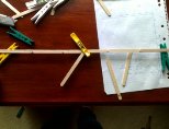
The design procedure was completed over a 2 week period allowing sufficient time for segment to dry before moving onto the next. Heavy duty pegs were used to fasten the joints that had already been sanded to allow for maximum strength in the joints.
As the design took shape, I made several smaller models and tested the joints to come up with a final design for the joints that would allow for more weight to be added before the joints failed. Failure in the joints would mean that it wasn’t the truss design that caused the failure, but a failure in the construction of the truss.
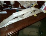
After allowing 24 hours for the 1 layer truss to dry the pegs were then removed. As the image illustrates the truss consists of one smaller heavily layered triangle and 2 larger reinforced triangles. The top side when under a pinpoint force will be under compression and the bottom tension. The central joint that will be directly under the metal element issuing the force was to be constructed so that the glue joins if they were to fail would not be able to move due to the surrounding sticks creating a ‘nest’ for the failed member.
The original design was to be compiled of 12 layers each consisting of 18-19 sticks. But after weighing the truss structure it was calculated that the truss would have a final weight of over 300grams which would lead to a decrease in efficiency. This was therefore reduced to an 8 layer truss that weighed 220 grams.
When designing the truss care was taken into using sticks that were not only straight but did not contain any knots or weak points, these sticks were discarded.
After the truss was completed all that was needed was to place angled bracing on the truss to stop any bending in the beams under compression. But throughout the whole design efficiency was always key and when bracing was placed on the structure it was placed in selected areas as once again placing sticks in places that was not needed would lead to a decrease in efficiency. Decking was also placed on the end supports to allow for even distribution of force throughout the layers.
The final design structure was 54cm long and 10.5cm wide it had an average depth of 5cm and weighed 220grams.
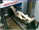
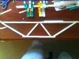
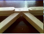
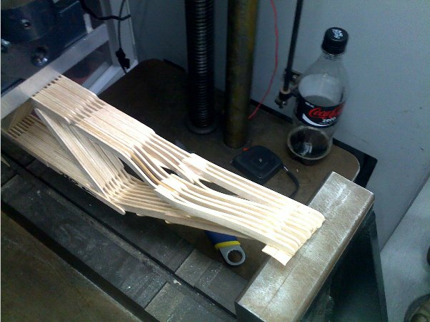
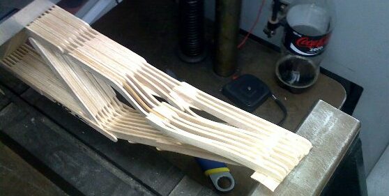
Nic’s design held a weight of 224kg and had a final efficiency of 1020. It did not shear or snap at any member, but bowed in the second third of member C-E. This member did have angled bracing to stop bowing and this brace did not snap it was only the glue joins in this brace that failed. The truss ballooned out at the point when 2.2kN of force was applied. It was at this point that the test was stopped.
If the experiment was to be completed again I would have braced this area more heavily but from what I had researched I thought the amount of reinforcement already applied would be sufficient as to negate any bowing in this area.

awesome bridge dude! 🙂
Excellent work!
I am interested in this quote:
“But after weighing the truss structure it was calculated that the truss would have a final weight of over 300grams which would lead to a decrease in efficiency.”
Why would the increase in mass contribute to a decrease in efficiency? Surely this would occur ONLY if there was not also an increase in strength?
The extra layers are not empty calories – they contribute to the strength of the bridge as well as adding to the width of the bridge. This second point would have helped limit the sideways bowing (I assume this is what you meant by “ballooned out”) where the load was applied, so could well have increased the efficiency.
Hey, So im the guy that made the bridge and just found it out on here.. Ok so i yes i understand what you are saying but it got to a point where the deadline for the bridge was soon and by adding too much weight to it and not letting it dry the glue wouldn’t dry and it would add to the weight.. I didnt have any g clamps so i had to use pegs… This is what caused it to bow out because every second glue wasn’t as strong as its previous.. Thats why it bowed.. If i had used g clamps i would have got a better score..
There was also limits to the bridge width and height in the competition..
very nice creation.
sir, i m going to design same bridge as you have been designed. Sir i request you to plse help in preparing my popsicle bridge. Sir i want to know the procedure of how to make it..??
please help me..its urgent
This is like the smartest bridge design I’ve seen in my entire life. Well done mate. Going to need to kinda borrow this design for a physics project if you don’t mind. Which I hope you don’t mind at all.